Connected Interaction Kit Circuit Diagram The following simple thermistor based temperature indicator does exactly this. The value of R3 is low and that of R4 is high at a comparatively low temperature. During the positive half cycle of the mains voltage, there will be a voltage across R3-D3 that is high enough to illuminate the green LED.
Temperature sensing with PTC thermistor is chosen based on the temperature range and the PTC's value. 2. Operate within the linear output voltage swing (See A OL specification) to minimize non-linearity errors. 3. The reference voltage, Vref, can be created Step-by-step circuit design of common op amp building block circuits. TI Designs

PDF Temperature Sensor Design Guide Circuit Diagram
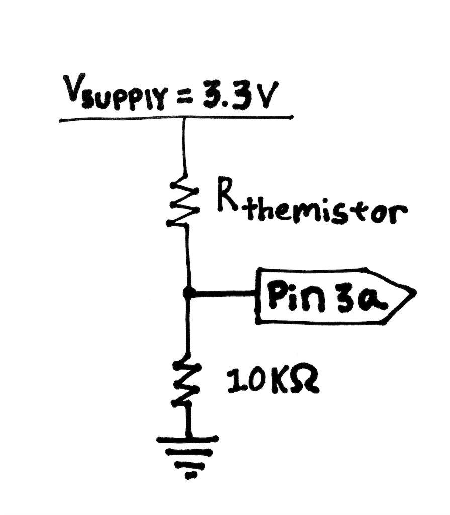
NTC thermistor circuit. The simplest circuit to measure temperature with a thermistor is to use the thermistor as part of a resistor divider circuit, as shown in Figure 1. Figure 1. NTC Thermistor Circuit. In this circuit, the NTC thermistor and the resistor form a voltage divider network. As the temperature changes, the resistance of the NTC Design Description This temperature sensing circuit uses a resistor in series with a negative-temperature-coefficient (NTC) thermistor to form a voltage divider, which has the effect of producing an output voltage that is linear over temperature. The circuit uses an op amp in a non-inverting configuration with inverting reference to

Temperature sensing with NTC thermistor is chosen based on the temperature range and the NTC's value. 2. Operate within the linear output voltage swing (See A OL specification) to minimize non-linearity errors. 3. The reference voltage, Vref, can be created Step-by-step circuit design of common op amp building block circuits. TI Designs
Temperature Sensor Circuit using Thermistor Circuit Diagram
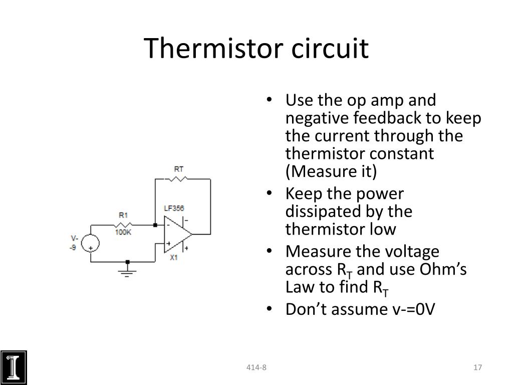
Sensors, Thermocouples, RTD Circuits and Thermistors A complete listing of products offered by Microchip Technology Inc. and their corresponding data sheets can be found at www.microchip.com. Precision Temperature Measurement with Silicon IC Sensors, Thermocouples, RTDs and Thermistors 6 Temperature Sensors Design Guide Temperature Sensors Figure 3. The current excitation of a thermistor. Another option is to set the gain but use a dynamic excitation current. So, as the signal level from the thermistor changes, the excitation current value is changed dynamically so that the voltage generated across the thermistor is within the electronics' specified input range.