
Electric Bike Controller Explained Circuit Diagram A bicycle (This one is a 20in BMX copy with fat tires to sustain those speeds) A Brushless motor from a hoverboard; A BLDC motor speed controller for electric bike; Throttle assemble; Battery pack; Spocket; Chain; Footrests; Tools: Drill machine and bits; Basic pliers; Soldering tools; A 3D printer (Just if you want to built customized 3D

$2/5pcs 2Layer & $5/5pcs 4Layer PCBs: https://jlcpcb.com🔥This PCB had some fails but I've fixed those in the final schematic so check below. It could go wa A typical DIY e-bike kit includes essential components like a motor, battery, controller, and wiring, making it easier to convert a standard bicycle into an electric one. wheel if necessary. Install the Motor: Depending on the kit, mount the motor in the wheel hub or attach it to the bike frame. Connect the Controller: Securely connect the

How to make Electric Bike Motor Controller using Arduino Circuit Diagram
Next, mount the battery and controller near the motor, making sure they are easily accessible. Connect the power cables from the battery to the controller, and then connect the controller to the motor. Building an electric bike from scratch typically takes several weeks to several months, depending on the complexity of the design, the

This DIY electric bike conversion guide will teach you how to convert your motorcycle into an electric bike with a few electrical components. The creator had an old regular motorcycle but converted it into an e-bike using a BLDC 48 volt 750-watt motor, a high-voltage battery and other supplies.

Homemade E-Bike Brushed DC Motor ESC Circuit Diagram
Get 10 PCBs for Only $5 (First Order Completely Free) https://www.pcbway.comIn this video I am going to show you how to make a powerful PWM speed controller I designed this controller for my Crystalite Sparrow 48V electric bicycle hub motor. The core function of a DC motor controller is to periodically read the throttle setting and adjust the current being supplied to the motor. It does this with a technique called pulse-width modulation or PWM (more on this later). An alternative way for 250 Watt 24volt brushed motor controller for electric bicycles. Here I have used a 6V to 90V 15 amp PWM motor controller to control my
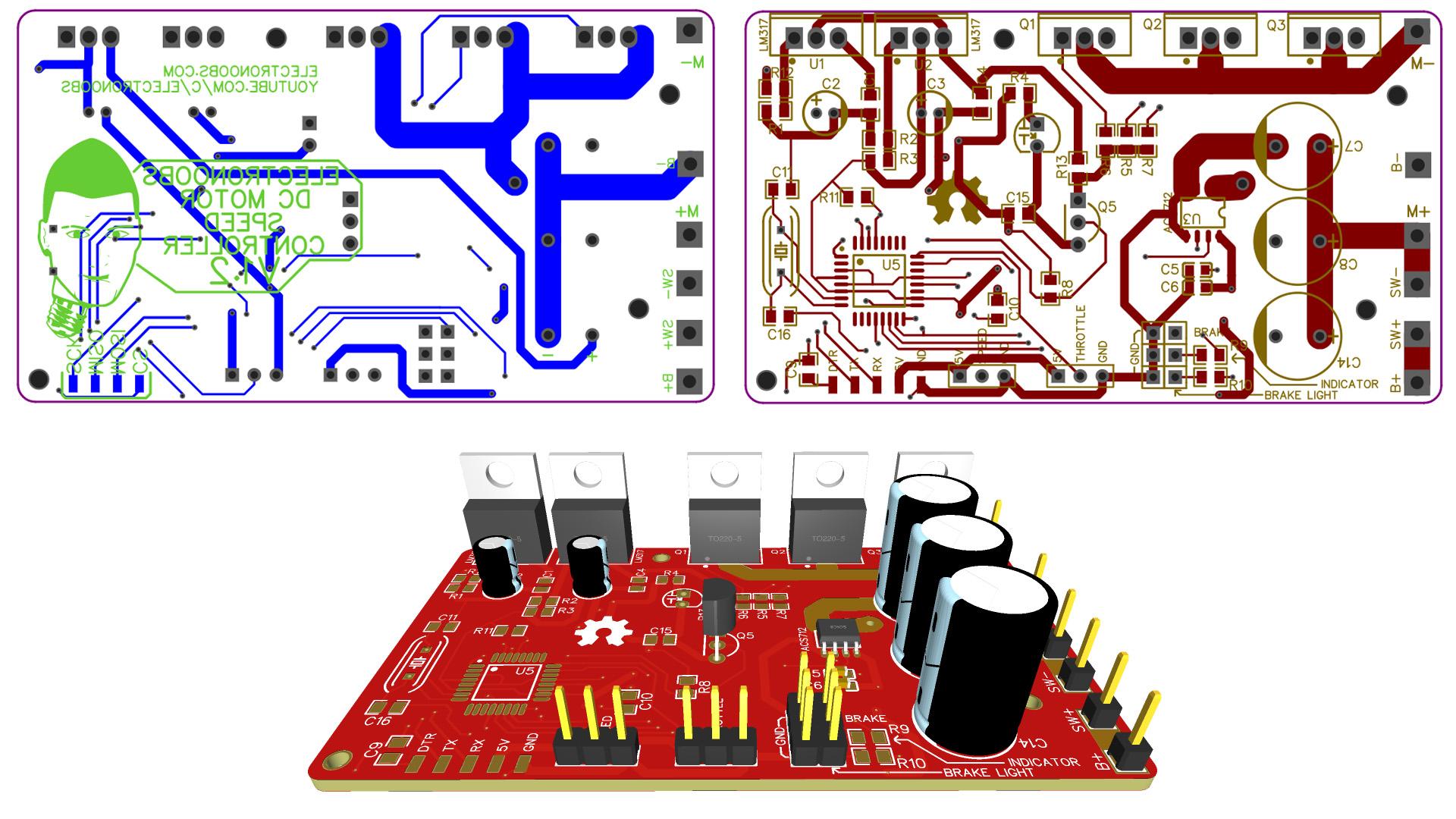
Electric Bike Motor Controller Circuit Diagram: This schematic is designed in the Cadsoft Eagle 9.1.0 version. If you want to learn how to make a schematic and PCB then watch my Tutorial. The MC33151 library can be downloaded by clicking on the download. This is a very simple and basic program. A variable resistor is connected with the
