
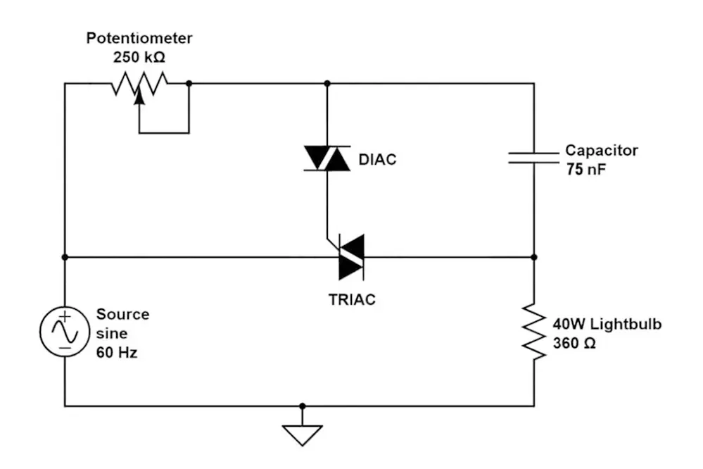
Figure 5 from Power Quality Impact of Residential LED Lighting Systems Circuit Diagram The circuit diagram presented above is an classic illustration of a dimmer switch, where a triac continues to be employed for managing the depth of light. When AC mains is provided to the above circuit, as per the setting of the pot, C2 charges fully after a specific delay supplying the necessary firing voltage to the diac. By carefully following this process and considering the safety precautions, you can successfully build a 220V AC light dimmer circuit with triac control. Adjustments to the potentiometer will allow you to control the intensity of the connected incandescent bulb. References: TRIAC dimmer, circuit design help (resistive load)

Working of Arduino Lamp Dimmer Circuit. Below are the pictures of showing three stages of dimming the AC bulb using Arduino and TRIAC. 1. Low dimming step . 2. Medium Dimming step . 3. Maximum Dimming step: This is how an AC Light Dimmer circuit can be built easily using TRIAC and optocoupler. A Working Video and Arduino Light Dimmer Code is
Simple Lamp Dimmer/ Fan Regulator Circuit using a Triac Circuit Diagram
The Diac and Triac can be connected in one of two ways to create a light dimmer. In the first, a DC voltage source is fed into the Triac, and the output of the Triac is connected to the Diac. The Diac then controls the amount of power being sent to the light bulbs.

After a couple of hours of making this project, this is our output of the circuit. It was indeed a simple light dimmer project. A simple can make it a better solution rather than a complex one. We test it in a 220V AC source so that we will know it will work or not. Take note that this is the first time we test in a 220V AC source.

Dimmer circuit using SCR Circuit Diagram
A simple Triac can do the work for you. Triacs are used in this circuit as a dimmer as they are easy to design and control, and are very much economic due to their high efficiency and low buying costs. This is the circuit diagram of the simplest lamp dimmer or fan regulator. The circuit is based on the principle of power control using a Triac. In this tutorial we will design a circuit using TRIAC and optocoupler to make a 220V AC Light Dimmer or AC Fan Speed Controller using Arduino. WARNING: This circuit is connected directly to the mains AC voltage. You must care about all safety precautions before using the device.