
Fm Modulator Circuit Circuit Diagram Next, we can adjust the C5 in the frequency generator circuit. To control the frequency from 87MHz to 108 MHz. And the frequency of the incoming sync with the frequency of the generator itself. Therefore, the frequency deviation of the signal received from the antenna to the audio signal. Which the frequency modulation is across the VR1 + R5. With a little cleverness, you can have a modulation signal change how fast the capacitor is charged and discharged, which in turn effects the oscillator frequency. This can be done digitally too. For FM, use a hardware PWM generator built into a micro, and adjust its period based on the modulation signal. For AM, a hybrid approach is possible.
The FM receiver circuit diagram using transistor operates on the principle of frequency modulation. It is able to receive radio signals in the frequency range of 88MHz to 108MHz. The circuit consists of a few components, including a high-frequency transistor, an inductor coil, and a capacitor.

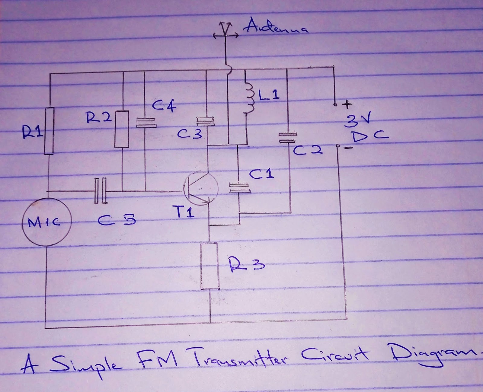
Design of FM transmitter and receiver circuits Circuit Diagram
We have also designed a simple stereo amplifier circuit. FM Frequency Ranges. Frequency modulation is used in a radio broadcast in the 88-108MHz VHF frequency band. This bandwidth range is marked as FM on the band scales of radio receivers, and the devices that are able to receive such signals are called FM receivers.
This tutorial explains circuit designing using a 555timer to generate a frequency modulated wave. Along with 555 IC timers, the circuit is designed around a Wien Bridge Oscillator circuit and a clamping circuit. Out of many methods of frequency generation, this tutorial covers one of the simplest and most efficient circuits. From its generation to modulation, the wave suffers minimal
How to Build an FM Radio Receiver Circuit Diagram
FM radio is transmitted with a process called frequency modulation. With frequency modulation, the audio signal is modulated (varied) by a high-frequency carrier signal. FM radio signals are transmitted at very high frequencies (88 - 108MHz). We can use an FM receiver to detect and de-modulate the FM radio signal.
